SPHinXsys architecture overview
SPHinXsys defines a collective objects and methods to applied as libraries
for a multi-physics computation,
which is constructed and carried out in an application code.
The core object and method are SPHBody
and ParticleDynamics, respectively.
While the former defines spatial and topological relations between particles,
the latter describes physical dynamics of them.
Constructing a SPHinXsys system
As shown in the figure below,
the first stage is creating all SPHBody s based on their realizations.
There are RealBody s modeling fluid and solid bodies,
and FictitiousBody s modeling observers
which collecting data from RealBody s during the computation.
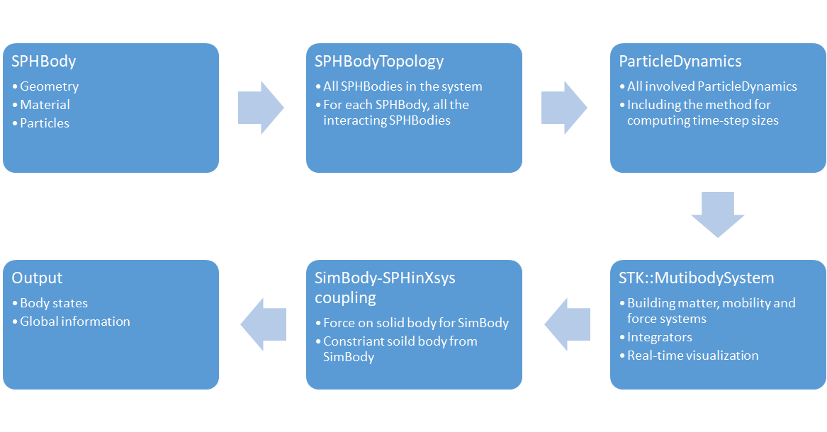
Constructing a computation with ordered stages
At the second stage, the topology of SPHBody s is constructed.
It describe, for each SPHBody, all the interacting SPHBody s.
After this, all ParticleDynamics will be defined.
Specifically, each realization of ParticleDynamics
corresponds all the discretized right-hand-side terms of a fluid or solid dynamics equation.
If SPHinXsys is coupled with SimBody, one need create a SimTK system in which all matters,
mobility and forces are defined. The SimBody-SPHinXsys coupling,
as a realization of ParticleDynamics,
such as computing forces on solid body for SimBody
and imposing constraints of solid body by SimBody, are defined in the next stage.
Finally, Output is created to specify the data will be saved in file during the computations.
Carrying out a computation
The computation is carried out by using an integrator defined in the application. There are three layers in the main integration step according to their the time-step sizes. While at the innermost layer the solid dynamics equations are integrated, at the middle layer the acoustic pressure relaxation of the fluid is computed and at the outside layer the effects of fluid viscosity is updated. The FSI is imposed at the middle layer and the coupling with Simbody is implemented at the innermost layer.
The below figure shows a flow diagram to represent the successive steps involved in a complete execution.
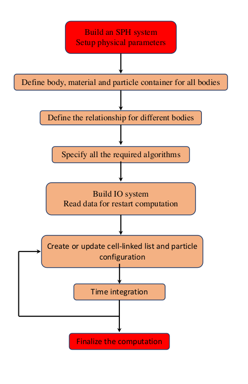
Workflow diagram for the implementation of SPHinXsys applications